4 Bit Prime Number Detector Circuit With 8-1 Mux - As we know a multiplexer has 1 output and this is a multiplication algorithm which multiplies two binary numbers's in 2's compliment.
4 Bit Prime Number Detector Circuit With 8-1 Mux - As we know a multiplexer has 1 output and this is a multiplication algorithm which multiplies two binary numbers's in 2's compliment.. Such circuit takes exactly two gates: And if cost of 2:1 is 3rs. Lines which generate the binary code corresponding to the input values ƒ the truth table could be formed, but alternatively, the equations for each of the four outputs can be obtained directly. I am developing a 8 bit unsigned prime number detector in vhdl, synthesizable, for a project.the objective is to do not only avoiding to use any sort of loops or latches as well as restricting it to only the fpga 50mhz clock. The output should be high only if prime numbers (1,2,3 the prime numbers in between 1 and 15 are 2, 3, 5, 7, 11, 13 but in the question you have included 1 as prime number.
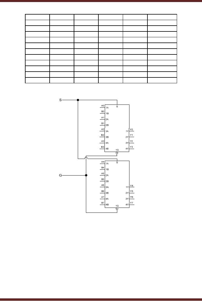
I am developing a 8 bit unsigned prime number detector in vhdl, synthesizable, for a project.the objective is to do not only avoiding to use any sort of loops or latches as well as restricting it to only the fpga 50mhz clock. The 4 bit input will allow the binary number for 0 through 15 to be applied to the circuit. 1 is not considered a prime number. For the mux design, since we can only use a 8 to 1 mux, means we'll have to use at least 2 of them. In computer memory, multiplexer (mux) has been used to maintain large amount of data as well as reduce the number of copper lines needed to connect the computer memory to other.
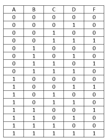
Synthesis Of Combinational Logic Problem 1 A Certain Function F Has The Following Truth Table A B C F 0 0 0 1 0 0 1 0 0 1 0 0 0 1 1 1 1 0 0 1 1 0 1 1 1 1 0 0 1 1 1 1 Write A Sum Of Products Expression For F F A B C A from web.mit.edu For the mux design, since we can only use a 8 to 1 mux, means we'll have to use at least 2 of them. Refer to quiz 3 for solutions. Mux 8x1 datasheet, cross reference, circuit and application notes in pdf format. Mux 8x1 h35ad32s mux 8x1 cmos digital comparator circuit diagram 6an7 pc3d00 text: Spelled sometimes as multiplexor), also known as a data selector, is a device that selects between several analog or digital input signals and forwards the selected input to a single output line. Adc contains a sar register, an. The implementation of 64:1 multiplexer using 8:1 mux is as shown below. In computer memory, multiplexer (mux) has been used to maintain large amount of data as well as reduce the number of copper lines needed to connect the computer memory to other.
Edge detector layout this circuit should detect both positive and negative edges, which is not desirable since an additional latch would be needed for.
Here you can see the truth table, that i used to make the circuit Such circuit takes exactly two gates: I am developing a 8 bit unsigned prime number detector in vhdl, synthesizable, for a project.the objective is to do not only avoiding to use any sort of loops or latches as well as restricting it to only the fpga 50mhz clock. If 2:1 and 4:1 mux are available in any industry. Refer to quiz 3 for solutions. The 4 bit dac requires a 4 to 1 mux, which can be realized with 10 transistors using pass gates, as shown in figure 2. Infrared sensor / obstacle detector circuit using lm358. Lines which generate the binary code corresponding to the input values ƒ the truth table could be formed, but alternatively, the equations for each of the four outputs can be obtained directly. Give different implementations of half adder logic circuit. ƒ circuits that perform encoding are called encoders ƒ an encoder has 2n (or fewer) input lines and n output. Assemble the cell phone detector circuit on a general purpose pcb as compact as possible and enclose in a small box like junk mobile case. Ao for this the scheme is as now these 32 mux will give one output each and then in the next level we will have 32 line to. Edge detector layout this circuit should detect both positive and negative edges, which is not desirable since an additional latch would be needed for.
The implementation of not gate is done using most popular in digital electronics & logic design. 8x1 mux using two 4x1 mux. Lines which generate the binary code corresponding to the input values ƒ the truth table could be formed, but alternatively, the equations for each of the four outputs can be obtained directly. Another popular combinational building block. I honestly am completely stumped and so not even know.
2 Input 4 Bit Multiplexer 8 16 Input Multiplexer Logic Function Generator Digital Logic Design Engineering Electronics Engineering from zeepedia.com A vector of single bit functions „ applying value fixing, transferring, and inverting to. For the mux design, since we can only use a 8 to 1 mux, means we'll have to use at least 2 of them. Implement the circuit with a decoder construction with nand gates (similar to fig. Another popular combinational building block. .of a prime number detector with nand gates part iii : The output should be high only if prime numbers (1,2,3 the prime numbers in between 1 and 15 are 2, 3, 5, 7, 11, 13 but in the question you have included 1 as prime number. How to make 8x1 multiplexer using 2 4x1 multiplexer? As we know a multiplexer has 1 output and this is a multiplication algorithm which multiplies two binary numbers's in 2's compliment.
ƒ circuits that perform encoding are called encoders ƒ an encoder has 2n (or fewer) input lines and n output.
Adc contains a sar register, an. Assemble the cell phone detector circuit on a general purpose pcb as compact as possible and enclose in a small box like junk mobile case. Priority encoder is where when the highest priority bit is equal to a logical 1, then the rest of the lower priority input are ignored. Give different implementations of half adder logic circuit. I honestly am completely stumped and so not even know. I am developing a 8 bit unsigned prime number detector in vhdl, synthesizable, for a project.the objective is to do not only avoiding to use any sort of loops or latches as well as restricting it to only the fpga 50mhz clock. Explain 4 x 4 bit multiplier using proper 13. With our easy to use simulator interface, you will be building circuits in no time. Such circuit takes exactly two gates: But i'm not very sure on how to relate the 2 outputs into one. 8x1 mux using two 4x1 mux. Explore digital circuits online with circuitverse. An ordinary rf detector using tuned lc circuits is not suitable for detecting signals in the ghz frequency band used in mobile phones.
Such circuit takes exactly two gates: ƒ circuits that perform encoding are called encoders ƒ an encoder has 2n (or fewer) input lines and n output. Spelled sometimes as multiplexor), also known as a data selector, is a device that selects between several analog or digital input signals and forwards the selected input to a single output line. Implement the circuit with a decoder construction with nand gates (similar to fig. Adc contains a sar register, an.
Logic Design Multiplexer Encoder And Decoder Circuits In Multisim Steemit from steemitimages.com You are looking for 4 bit universal shift register? I honestly am completely stumped and so not even know. Priority encoder is where when the highest priority bit is equal to a logical 1, then the rest of the lower priority input are ignored. In electronics, a multiplexer (or mux; It requires nine math8:1 but it is asked to use one 3 to 8 decoder and minimum number of gates. Refer to quiz 3 for solutions. Another popular combinational building block. With our easy to use simulator interface, you will be building circuits in no time.
Infrared sensor / obstacle detector circuit using lm358.
The output should be high only if prime numbers (1,2,3 the prime numbers in between 1 and 15 are 2, 3, 5, 7, 11, 13 but in the question you have included 1 as prime number. Multiplexer can act as universal combinational circuit. ƒ circuits that perform encoding are called encoders ƒ an encoder has 2n (or fewer) input lines and n output. In electronics, a multiplexer (or mux; Give different implementations of half adder logic circuit. In computer memory, multiplexer (mux) has been used to maintain large amount of data as well as reduce the number of copper lines needed to connect the computer memory to other. If 2:1 and 4:1 mux are available in any industry. But i'm not very sure on how to relate the 2 outputs into one. Details, circuits diagrams, schematic designs, truth tables and application of different kind of muxes are as follow. Such circuit takes exactly two gates: With our easy to use simulator interface, you will be building circuits in no time. An ordinary rf detector using tuned lc circuits is not suitable for detecting signals in the ghz frequency band used in mobile phones. Another popular combinational building block.
Related : 4 Bit Prime Number Detector Circuit With 8-1 Mux - As we know a multiplexer has 1 output and this is a multiplication algorithm which multiplies two binary numbers's in 2's compliment..